Wednesday, 11 January 2012
Saturday, 12 November 2011
Wednesday, 19 October 2011
Tuesday, 15 March 2011
Unit: BA3: Project 2: Rigging Fundamentals
This project I found of a particular interest, for it offered me the opportunity to learn both an entirely new skill set and the means to acquire a new tool to use within the process (in the form of Maya.) This essentially afforded me the ability to obtain that knowledge (gained throughout this very brief and simple project) and implement it, with greater complexity, to future work, both personally and professionally.
The primary task assigned through this project, was to take a simple piece of geometry (in this case, a pair of legs that had already been created within Maya) and then apply a 'rig' to that model, before completing the work by animating the rig (focusing on a form of bipedal gait, or movement, that would accurately and believably 'reflect' the object being animated, which were humanoid legs in this case.)
The project required us to take what we had learnt from our previous animations and then apply that knowledge to this work; unlike the majority of my peers, however, I had chosen to create my previous animation within two-dimensions (whilst still within a digital format) which meant that other than the simple bouncing ball that I had animated previously, I had no prior experience with animating a '3D' object, which meant re-teaching myself the process again. The 'twelve principles' (or fundamentals) of animation, however, I was aware of before this course and so this understanding proved useful when working on the final section of the work. This would be my second attempt at using Maya.
The 'Rig'
With the exception of perhaps research and conceptual art (along with any other processes of pre-production) and the actual development of modelling itself, the project esssentially tasked us with performing (albeit rather simply) a large process of many film and game design production 'pipelines', which is 'rigging' and 'animation'. The 'rig', is essentially the underlying framework that 'drives' the rest of the model, comprising of the skeletal structure and the controls that manipulate that said structure. The principle of animation of 'pose to pose' is reflected in the method to which you animate objects in Maya; by establishing a series of poses along a timeline (and setting what is known as a 'keyframe' for each individual pose) Maya will proceed in creating the 'inbetweens' (or the motion/series of movements that connect one pose to another) creating the animation. Manipulating where each 'key-frame' (and pose) is, along the timeline (or by affecting the 'animation curves' within the 'Graph Editor') you can affect the speed to which the motion takes place (altering the number of frames per second will aslo affect the timing and overall fluidity of your animation.) The main focus, however, within this section of the blog, will concern the first process of the work, which is 'rigging.'

My first issue was in attempting to accurately recreate the skeletal structure of the human leg (which whilst I managed to do during my first attempt, was met with later concerns as my having adjusted the position of the joints after having placed them, caused unforseen irregularities.) Greatly simplifying the skeletal structure meant that I was still able to achieve a fairly accurate and believable form of bipedal movement.
The first 'step' within the process of creating the rig, is establishing the initial 'skeleton'. The 'skeleton', within Maya, is a series of interconnecting 'joints', whereby the 'bones' (or the objects connecting each joint together) serve no purpose other than as a visual aid for the user creating the rig, as all movement is centred around the joints themselves. The joints are created by using the 'Joint Tool'. The joints are then connected/linked together within a hierarchy or 'joint chain' (often referred to as a 'parent to child' relationship, whereby the 'parent joint', controls the actions of each 'child joint', further down the hierarchy; this is achieved through connecting one joint to another by means of a 'Parent constraint.') The 'root' joint, is the single most 'dominant' joint, in that it controls the rig in its entirety and is usually located at the centre of the rig/'skeleton' (which in the case of humanoids, is often within the 'torso'.)
There are two primary methods of manipulating the rig, one is known as 'Forward Kinematics' and the other, 'Inverse Kinematics' (as the names suggest, each process is a reversal of the other, though both establish control over the connected joints through the creation of a 'linked' hierachy, simply offering the user an alternative form of control.) The process of Forward Kinematics, very simplistically, means that any movement of the 'parent joint', will in turn affect the translation (or 'location' within a virtual space) of all joints connected (or 'parented') to that joint, but it will not affect any other form of movement within the joints, such as rotation. This 'method' offers greater control by the user, over the rig and is often used where such control is needed (the human arm, for example, would be moved by first manipulating the 'shoulder joint', then the joint of the 'elbow', then the joint affecting the wrist and in turn the individual joints within the fingers, if applicable.) Alternatively, 'Inverse Kinematics' performs the opposite, whereby the user will establish what is known as a 'handle' (or 'IK handle') within the last joint of the 'IK chain', creating a node that is known as an 'end effector' (positioned at the joint you intend to move to control all other joints connected between it and the starting joint.) Selecting a joint (which establishes the point of connection) and then choosing the end joint (completing the hierarchy) will allow for all or either of the translation and orientation information of the joints inbetween, to be affected, upon moving the joint where the 'IK handle' is located; the end effector essentially drives this movement. For example, if you connected the joint located at the 'hip' to the 'ankle joint', moving the foot will in turn move the 'knee joint', that is located in between. In the rig that I created for the legs, there are two alternative forms of IK handles in use, one that is known as a 'rotate plane IK handle' (abreviated as 'ikRP solver') and the other, a 'single chain IK handle' (or 'ikSC solver'.) The difference between the two, simply, is the way in with the end effector attempts to move towards the position of the handle within it's chain; one moves according to the orientation and position of it's handle (the 'ikSC solver') whilst the other moves only to match the position of it's IK handle (the 'ikRP solver'.) I'll explain this in slightly more detail and with examples further within this blog, when commenting on the process of creating the 'Reverse Foot Lock' (the process of connecting what is referred to as the 'Reverse Foot' to the joints of the foot itself, 'locking' them into place.)
In the image depicted above, I have very crudely sketched the basic skeletal structure that comprises the human 'leg.' The diagram and accompanying annotation, refers to the first issue that I had encountered when beginning the process of creating the rig for the legs. The initial placement of the joints themselves is extremely important and requires a degree of accuracy when deploying them the first time around. I found out, later on within the process, that the repositioning of any joints (subsequent to their placement) might be met with future difficulties and unforseen irregularities when attempting to link or 'bind' them together, or during any form of movement (not always, but more often than not.) The first rig that I had created for the legs (before the second attempt that you can see the images of above) saw me position the joints in such a way as to faithfully re-create (or as accuratly as possible) the natural angles of the joints and the bones within the human skeletal system. To avoid such complications, I simplified the structure of the skeleton (by altering the translation between the joints of the 'knee' in particular, essentially 'straightening' what we percieve as 'bones') which did not affect the bipedal gait of the 'character', maintaining a degree of believability to the final movement (whilst making the process of rigging and animating simpler.) The joints could be placed in such a way as that which I described as having done for my first rigging attempt, though the lack of muscle deformers perhaps would make the walk appear odd, especially without the skin being shown. The simplified skeletal system seemed to work fine and appeared to be a solution to the 'issue' (if to serve nothing more than just to simplify the process.)

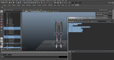
In the image above (which depicts the final rig, with the exception of the control for the pelvis and spine, that was added later) you can see the 'set-up' that I had established when creating my rig (which includes the initial skeletal system, comprising the joints and the connecting IK handles and also a series of 'outer controls'.) The aforementioned 'controls' were created to allow movement of the joints in a 'non-destructive' way (as I mentioned previously, that manipulating joints, subsequent to their placement, can lead to difficulties.) The placement of each joint and control system was followed by 'freezing the transformation' and so when I want to return to a particular default position for the character, I have most of the settings set to zero, so upon manipulating the character and then wanting to return to the pose as depicted within the image above, all I have to do is alter the values of 'X', 'Y' and 'Z' for the translation, orientation and scale, to 'zero' (this process is known as 'zeroing out'.) Naming conventions and colour co-ordination, are also necessary for maintaining a degree or organisation across your interface; as you can see in the image above, I have named each joint and related system of control, based on what it represents; seperating the names based on whether they are on the right of the body ('R') or the left ('L.') I have also divided the rig and the geometry (the 'skin' of the legs, as seen) into seperate layers, that have not only been named but have also been colour co-ordinated (with blue representing the right of the body, red portraying the left and green depicting the middle.) By selecting an object you can assign this particular object to a new layer very easily and as is the case in Photoshop, you can choose to hide layers (or in Maya, use them as a reference, meaning you can see them, but not click on them or affect them in anyway.)
The two main forms of control that I want to comment on, are the controls that manipulate the knee and what is known as the 'Reverse Foot' (named so due to the order in which you create the joints for this control, which, essentially, is a reversal of the joint creation for the foot itself.)

Using the tool that I explained previously (known as the 'Parent' constraint tool, or by simply pressing 'P' after having selected one joint, the 'parent' joint and then shift + selected another joint, the 'child' joint) I was able to link each joint of the leg into a hierarchy; initially beginning with just one leg, from the hip joint and parenting down each joint untill reaching the toe and then copying this leg, by using the tool 'Mirror Joint' (though only after having completed the IK handles for the leg.) I then created the lower spine and pelvis between the two legs, which acts as the central, or 'root' joint, controlling both legs. In order to have predictable movement and essentially, control over the joint within the 'knee' section of the leg (specifically the orientation of the knee) I needed to create a seperate object that I could outwardly manipulate. To do this, I created a single shape of what are known as 'NURBS Primitives.'
The 'NURB Primitive' that you create can be any shape that you like (and the shape can be further manipulated by holding the right-click button and selecting the 'Control Vertex' option, allowing you to alter each vertex that comprises the shape, into a shape more suitable to your liking) the actual design of the primitive, however, is only based on how comfortable you are selecting it and perhaps it's aesthetic appeal; for the purpose of this simple rigging process, I chose to create a circle. Position the circle so that it is in-line with the joint of the knee (which is most accurately achieved by shifting between the different orthographic views) and this will be exactly what your final control for the knee will look like and it's translation to the rest of your rig. At this point, no IK handles have been created for the rig and so firstly select the 'IK Handle Tool' and then begin by clicking on the hip joint (noting that all of this process will be on one leg, before mirroring to create the other leg) and then simply left-click again onto the ankle joint (this will be where the IK handle will be located and essentially the 'end-effector.') Ensure that you change the default settings of the 'IK Handle Tool' from 'ikSC solver' to 'ikRP' solver before doing this (as this will allow for the desired movement in conjuntion to the knee, as it'll only affect the legs translation and not it's orientation, the latter control of which we will assign to the joint of the knee.)

Having created the the IK handle, connecting the hip joint, to the ankle joint; I then connected the newly added knee 'control' to the rig. Selecting the knee control and then holding shift and left clicking the IK handle (located within the ankle joint) you then constrain the two by selecting the tool entitled 'Pole Vector.' The purpose of this 'Pole Vector' simply allows you to manipulate the orientation of the joint chain that it is attached to, in this case (the hierarchy that we have established within the leg.) I was initially confronted with some difficulty during this process, as being my first ever time in rigging an object and again, third time in using Maya, I was initially unaware of the order that you connected the Pole Vector (from the joint chain) to the shape that you had established as the knee control; though through a process of trial and elimination, I came across the correct order. Similarly, when connecting the 'Reverse Foot Lock' to the foot (the process of which I will explain after the knee controls) I had encountered difficulty as I rushed the process, not considering, carefully enough, about the 'parent to child' relationship and instead connected the foot joints to the 'Reverse Foot Lock' (instead of the other way around, where the 'lock' controls the foot.) The order in which you select objects to constraint is very important for this reason.
Following the creation of the 'Pole Vector' constraint, you then change the IK handle settings from 'ikRP solver' back to the default setting of 'ikSC solver' (allowing this time, both the translation and orientation to be affected upon movement of the IK handle) you then create an IK handle from the ankle joint, to the 'ball' of the foot and then another IK handle from the ball joint, to the toe (completing the joint chain for this particular leg.)
The second (and final) control that I added to the knee, is entirely optional, with the whole purpose of this control simply being that it constrains the pole vector (or the knee control) to the geometry of the knee (though not specifically the outer skin, but a form of geometry that we must first define.) I refer to this as entirely optional, as the knee joint will still work as it should, without this added control, but this method will ultimately create less work for you later on in the process, when animating, as you won't need to keep moving the control (for the knee-joint) every time you move the leg forwards or backwards, as it'll be constrained to one area around the joint. Note also that this control should actually be created before attempting to create the 'Pole Vector', as you will be adjusting the position/moving the first control.
As was the case with the prevous control, first we must establish a shape to manipulate/constrain to the joint chain and so, again, I chose to create a circle (from the 'NURBS Primitives shapes.) Positioning this as carefully as possible around the geometry of the leg (the size of this circle will determine the distance of the pole vector from the knee joint)
Once you have positioned the circle and subsequently the previous control for the knee (so that the two are actually touching) you then 'Pole Vector' constraint the original knee control to the IK handle on the ankle joint (again by first selecting the control and then the handle.) Following this you then need to constraint the newly created circle, to the knee joint that it is surrounding (by first selecting the joint, then holding shift whilst left-clicking the circle and then finally clicking on the 'Point' constraint tool.) Finally, you select the second circle and then the 'Pole Vector' constraint and then click the 'Geometry' constraint tool; now whenever you move the joint chain, the 'Pole Vector' constraint (or knee control) will maintain it's position around the knee joint as it moves. You can then choose to 'hide' the circle than is constraining the knee control around the knee joint, by changing the 'Visibility' within the 'Channel Box' to 'off'; for the purpose of clarity I have chosen to keep them on (as is depicted within the accompanying screen-shots) to once again, highlight this process (as you can see with the horizontal circles surrounding the knee joints.)
The 'Reverse Foot Lock,' is simply the control that will manipulate tha various joints that we have already established within the foot; instead of creating a 'NURBS Primitives' shape for the control, this time we will simply create the shape of the 'lock' using the 'Joint Tool', creating the joint firstly for the 'heel' of the foot, then the toe, then 'ball' of the foot and then finally the ankle. Selecting the joint that you have created for the ankle within the Reverse Foot and then holding shift whilst left-clicking on the ankle joint of the foot itself, will allow you to 'Parent' the two. Contine to Parent constraint each section of the Reverse Foot to it's equivelent 'counter-part' on the foot itself, untill you have 'locked' the Reverse Foot into place. Controlling the Reverse Foot Lock (or the 'heel joint' of the Reverse Foot) will allow you to control the movements in there entirety for the foot itself (including the ankle, the 'ball' of the foot and the area where the toes are situated.)
For the purpose of clarity and simplicity, I have created the 'Reverse Foot' slightly below the location of the foot (revealing, exactly, the shape and direction of each joint within the 'lock', to one another) although ideally you'd want the 'lock' to mimic the exact position/translation of each joint, so that upon moving the control, the 'lock' will pivot as closely and as accuratly as possible with the foot.) Moving each of the controls seperately will ensure that you have created a 'successful' rig (making sure also that the newly 'mirrored' leg is correctly parented to the pelvis/lower-spine.)
The final step would be to use the 'Mirror Joint' tool, to copy the entirety of the leg that you have rigged (after having first selected all of the leg) and then simply re-create each of the controls for that leg onto the second leg (as whilst the joint chain and IK handles are mirrored across, the outward 'controls' are not and if there is a way of doing this short of 'copying and pasting' and then re-attaching the controls to the rig, I am currently unaware of it, athough I will look further into it.)
An option for a final control for the legs, is available, in the form of a 'Location Node' (which you can see as the large circle beneath my rig) which essentially allows you to move the leg/model in it's entirety, though I later found no use for this control for the animation that I was creating (that required no forward/backward motion, but simply movement on the spot.) Another control that isn't depicted within the screen-shots untill later on within the process of animating the rig, is the control I created for the lower spine (or more specifically for the 'root' joint that is located within the centre of the pelvis.) During the process of animating the 'walk cycle' for the rig I had created, I realised that if I was to instill a level of believability, then I would need the pelvis to rotate 'upwards' and 'downwards' (pivoting from it's centre) to reflect the shift in weight that the human leg experiences during any form of gait. For this latter control I altered the shape of the NURB Primitive slightly, for greater clarity in it's use (any additional controls are created using the methods highlighted/commented on, earlier within this blog.)
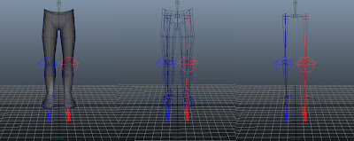
The three images directly below, depict the final rig (with the exception of the 'lower-spine/pelvis' control that was added later) in both a frontal, three-quarters angle and in profile (with each image also displaying the outer geometry that comprises the 'skin' of the model (the 'Smooth Shade All' and 'Wireframe on Shaded' both selected) the 'Wireframe' of the model (with 'Wireframe' only selected) and finally with just the rig itself (including the 'controls') with all other geometry hidden.


The Process of 'Skinning'
'Skinning' is fairly straightforward and simply refers to the process of 'binding' the underlying character rig (the skeleton and it's various controls) to the geometry/outward surface or 'skin,' of the model.
The simplest and most common/preferred method of binding the skeleton of the character, to the model's surface, is by first selecting the 'root' joint (which would be the centre of the pelvis in the case of the skeleton that I've created) you then hold 'Shift' and left-click the geometry of the skin (or the 'surface' of the model) and then under the Animation 'tab,' you have the tab 'Skin' and then the options 'Bind Skin' and then finally 'Smooth Bind.' Following the procedure outlined above, will result in you being able to make any of the controls 'driving' the rig move and have the surface of the model move with it. Alongisde this, Maya also applies what are known as 'Skin Weights', which control what area of the 'skin' moves with what joint (effectively how the surface of the model 'deforms' in conjunction with the movement of the skeletal structure or 'joints', beneath.) The issue with allowing Maya to control the 'influence' of the Skin Weights alone, will mean that Maya will define what it believes to be the most logical placement; which might (or will most probably) not correlate with what it is you want. The result of such a procedure on the rig that I have created, can be seen below as depicted by the screen-shots.

After binding the underlying skeletal structure to the surface of the model, we are left with irregularities in how the 'skin' deforms, upon moving the skeleton. To create more realistic surface deformations, we will need to edit the model's 'Skin Weights.'
The above image displays the calculations that Maya had applied to the model, upon 'smooth binding' the rig to the skin and as you can see, as I move the model, the 'calf muscle,' up to the back of each leg in particular, does not 'deform' in a convincing manor, which means that we will have to edit the Skin Weights manually (or more accurately, 'adjust' what has already been applied by Maya.) Upon researching further, however, I descovered a 'skinning' tool, that is new to Maya 2011 (the version of software that I am using) which is (what I believe) to be a more efficient method of binding the skin, known simply as the 'Interactive Skin Bind Tool', under 'Edit Smooth Skin.' This process is an alternative method of binding the surface geometry to the character (as opposed to the 'Smooth Bind' technique.)

The image above depicts this particular tool, which desplays various colours to denote the influence that each joint has over that area of the surface geometry (with 'cool' colours, such as blue, representing very little influence, whilst the 'warmer' colours, such as red, representing a much greater influence.) The systems of control that you see encasing the area of the joint that you are working on (which is the knee joint within the example above) allow for you to manually alter the entire range of the influence, very efficiently and intuitively, as opposed to painting individual 'strokes' to alter the Skin Weights.

The more 'traditional' procedure of painting Skin Weights, is a technique that I have still opted to deploy (not only to further edit the 'weights' themselves, but also because this is all entirely new to me, I have a desire to learn past skills that may well prove to still be useful and applicable to my working practises, as they are in this situation.)
Having already defined the 'parametres' of the Skin Weights themselves, for each of the joints (using the Interactive Skin Bind Tool) I am then able to further edit the 'weights' using the 'Paint Skin Weights Tool' under Edit Smooth Skin. Painting the Skin Weights is performed in much the same way as painting in Photoshop, you simply alter the size and intensity of the brush and where ever you paint white (the joint's influence will be applied) and where ever there is black, there will be zero influence (with the range/value of greys inbetween denoting the range of that influence, again, with pure white suggesting an influence of one-hundred percent.) Having completely altered the Skin Weights of the model, I was able to remove the undesired deformations in the surface geometry (upon moving the skeleton) which were depicted previously, within the third image above.
The 'Animation'
The process of animation, within Maya, very simply involves establishing, first of all, your initial 'Settings' for the entire animation and also for the 'Time Slider' and 'Playback;' which in the case for my animation, I had set to 'Real-time [25 fps]' (meaning it'll animate at twenty-five individual frames per second and playback at the standard form of time-keeping that we recognise as Real-time.) The overall time setting for the animation was set to 'PAL 25fps', which is the standard form of animating in Europe (or more accurately, Phase Altering Lines or '50hz' are the electrical current/television settings for many countries in and outside of Europe.) The second consideration when attempting to animate in Maya, is that it uses, primarily, the animation principle of 'Pose to Pose' (which I have explained in greater detail towards the beginning of this blog.) Creating a pose and setting what is known as a 'Keyframe' (by pressing the 'S' button, which appears as a red line on the time-slider) and then moving (or 'scrubbing') forward through the time-slider, posing the model again and setting another keyframe, will cause Maya to create the animation in between (also known as an 'inbetween'.) Setting the 'Auto keyframe toggle' to 'on' (as highlighted by the light blue circle in the diagram below) will automatically set a keyframe for the object selected, everytime you move or reposition that object (quickening the process.) Below the time-slider, there is also the 'range slider', which allows you, to essentially, adjust the amount of frames that are 'present' on the time-slider, to a different number on the range-slider, allowing you to focus on specific areas of your animation. All of the 'settings' that I mentioned previously, can be found within the 'Animation preferences' box (as highlighted by the red circle, in the image below.)

One of the main issues I experienced when I began animating in Maya (again, with this being my second ever attempt at doing so) was posing the animation, setting a keyframe, moving forward through the time-slider, posing the model again and setting another keyframe and so on, though the model (when played back) would fail to move at all. I later realised that the issue was to do with my having only one control selected when setting each keyframe (which not only meant that I had to keep track of 'multiple' time-sliders, as each object displayed it's own keyframes seperately on the time-slider, but also it was creating difficulties for the entire animation.) To overcome this problem, I needed to create my own custom 'button', that would allow me to select all the controls at once, so that I could place a keyframe on each control (avoiding the aforementioned issue.) I began to do this by selecting the 'Custom' tab (as highlighted by the green circle in the screen-shot above.)

Preferably with the Script Editor still open, you will need to very carefully select each control, one by one (by clicking on the first object and then holding shift whilst left clicking on each of the other objects, in this case, controls.) It is important that you don't click off any of the controls as you select them, or click on anything else, otherwise you'll need to repeat the previous step (clearing the history) and start this part of the process again. The screen-shot below depicts this 'step.'
Following this, you then place your cursor over the highlighted history (if the 'history' is not highlighted, simply do so now) and then while holding the left-mouse-button down, drag this information onto the Custom bar that you had opened previously; it'll now give you a few options, in which you select 'MEL', which will create a custom 'button' on the bar (as circled in blue, in the image below.)

Upon moving the model (which will automatically set a keyframe) remember to select all of the controls (via the button that you have created) and press 'S' to set a keyframe (which will in turn create a keyframe for each of the controls.) This procedure not only fixes the aforementioned complication but also presents the information within the time-slider, in much greater clarity (for although the image below depicts only one keyframe being set for the movement of any one control, a keyframe has in fact been set for all of the controls, whether they have been altered or not, as to denote their exact position on the time-slider.) The screen-shot below clarifies this process by highlighting the Channel Box in red (encircled in blue to emphasise this also.)

The 'Graph Editor,' also allows for much greater control over the entirety of the animation and, by manipulating the curves on the graph (each curve of which denoting a specific value of an object, such as it's translation, or orientation etc.) you can change both the positions and timing of your animation (as depicted in the screen-shot below.)

In the screen-shot below (the Graph Editor of which is highlited in green) I noticed that I had two 'tangents' (points on the graph, which represent keyframes, connecting the lines together) that were similar in value and so by placing them on the same value along the graph (in this case by typing the value of '-30', after having selected both of the tangents) I was able to 'smoothen' (or increase the fluidity) of the animation and the transition between frames. The two tangents in question (and the box to which I typed in the value) are encircled in blue.

As evident in this screenshot (below) you can also directly alter the curves themselves to create a smoother animation (and by clicking on an object within your viewpoint/on the model, the curves associated with that object will appear seperately in the graph below, offering you greater focus in adjusting the intricacies of the scene that you are animating.)

Upon reaching a degree of satisfaction with the animation, I could then return to the scene and alter the timing to quite a large degree (whether that involves increasing the pacing of the scene or indeed the length of time that the animation takes place within.) I noticed (at this point in particular) that I could now alter the walk cycle that I had created, which was far too slow and would need to be quickend (although I had purposefully animated it this way to begin with so as to help 'break down' the scene and individual poses.) The creation of the animation itself, involved me setting keyframes at 'strategic' locations along the time-slider (meaning that each main pose was animated on every twenty frames with the 'breakdown' poses directly halfway in between.) Animating in this fashion allowed for me to easily alter the entire ordering (if desired) and location of the keyframes along the time-slider; although I was able to do the latter and select all of the keyframes without altering at all the sequence of poses that had already been established. The movement of keyframes in this way was achieved by firstly selecting them all. Begin by holding the shift key and the middle mouse-button (at a desired point along the time-slider) and then drag across the time-slider, to select as much or as alittle as you like, before releasing both the key and button (you should be left with a red box across the 'selected' area of the time-slider, as the green box highlights within the example below.)

Upon releasing both the shift key and the middle mouse-button, you are then able to see four outward-facing 'arrows', select only the middle two by left clicking them; whilst holding down the left mouse-button, you are able to drag all the frames that you have selected, to the desired position (in the animation that I created, to speed up the 'walk-cycle', I moved each keyframe, one frame downwards within the time-slider, thus shortening the distance between each frame by one.)
Last-minute alterations to the animation included the addition of the lower-spine/pelvis 'control' (which was created slightly before the alteration to the speed of the animation, as outlined within the process above.) The additon of said 'control' allowed for me to add more believability to the bipedal gait that I had established, through compensating for the shift in weight (the result of the movement of each leg) by having the 'pelvis' rotate horizontally (upwards and downwards) which was initially quite exaggerated, though later made more subtle. With the animation largely completed, I was met with one, fairly annoying, fault (within the poses of the walk-cycle itself) which was that the right foot dragged (ever so slightly) forward before rising and then lowering again (whereas the left foot had no such issues.) I continued to alter the curves on the graph and manually change the pose within the view-port itself (matching the positions that the right foot was moving through) but it still continued to perform this awkward action. Time-constraints on this project, will mean that I will have to return to it on a later date, allowing me time to reconsider the complications and adjust accordingly.
The Process of 'Rendering'
'Rendering' simply refers to the procedure in which the software package that you are using (whether that is a 'third-party' programme, such as mental ray or in-built, such as Autodesk Maya's, Maya Software, the latter of which I used in this case) combines all of the elements in your scene (including the model surfaces, lighting, effects and the animation etc.) into a final image. The scene can be rendered into a series of frames (as opposed to a single image) by using a process known as 'batch render', which, depending on your settings, can either create a series of still images, representing each frame (which is almost always the technique deployed by professional production companies) or a final video file (in which my animation was the latter and saved as an '.AVI' file.)
In order to render the animation, first I needed to create what would be the final scene 'setup.' To begin with, I added a surface for the model ('legs') to animate on and I did this by first going to Create, then Polygon Primitves and then Plane and you can translate, rotate or scale this object to any degree that you like (though for this animation, it was important that the legs appeared to be on the 'ground', which the plane was representing.) I then proceeded to add lighting to the scene, in much the same way that I added the plane (which was simply under Create and then Lights) there are a few different options of lighting, though for the sake of simplicity, I simply used 'Directional Lighting' for the entirety of this animation. The result is an object that is created within your scene, that comprises of four arrows pointing within the same direction (denoting the direction to which the light be pointing towards.) It is important to note that you can manipulate the light source in many different ways, as you would any other object, though scaling the light does not affect it's intensity, instead this is altered bypressing 'Ctrl' and 'a' to bring up the 'Attribute Editor' (which will allow you to not only affect the lighting but alos turn 'on' shadows and manipulate the settings for this also, such as the level of quality or indeed intensity.) To preview what the final scene will look like (with these elements included) you can click on the button (encircled in blue, in the example below) entitled 'Render the current frame' (which will also tell you what rendering programme you are using.) The image below shows also the appearence of the light, as an adjustable 'object' within the viewport and next to it, the window that displays the rendered scene with the influence of the light source clearly visible.
Two buttons to the right of the 'Render the current frame' button (encircled in blue, below) is the 'Display Render Settings window'; which, as the name suggests, allows you to alter the final rendering settings (such as the size of the document, the quality of the image, the file format and of course the title of the file.) I left the changing of these settings untill I was ready to render the final animation, although it is important to be aware of these settings now (my final animation was saved as an '.AVI' file, with my 'Renderable Camera' set to the camera within the scene, as opposed to the default viewport camera views and the image size set to 'HD 720.)

I now needed to create the camera that would compose and frame the scene (for whilst each viewport has a camera by default, I intended to animate the scene in a way attune to my specifications.) Similarly to the addition of lights to the scene, the camera is accessed also within the Create tab (the camera that I chose to create, was the standard 'camera' option.) Much in the same way as the lights, an object is created to visually display this on-screen (in the shape and style of an old film camera) this object can also be manipulated in a number of ways, though for this animation, I simply consentrated on it's translation and rotation.
I decided, very early on within the process, that I was going to create a 'turn-table' type effect, in the way that the camera pans/moves around the scene; to do this, I created the virtual equivalent of a 'dolly' (a controlled system of moving the camera.)
To begin with, I needed to first define the area that I intended to 'attach' the camera to and the path to which the camera would move on; I achieved this by creating a NURBS circle and centring this in the area surrounding the model (or legs.) The size of the circle would determine how far away the camera would be positioned from the legs at all times (for the camera would animate, based on the movements of the circel, for in actual fact, it'll be the circle that we are animating.) By applying a Parent constraint between the camera and the NURBS circle, I was able to create the 'dolly' and thus the ability to rotate the circle and have the camera move with it. Setting a keyframe, with the camera facing forward, infront of the legs (at the beginning of the time-slider) and then by setting another keyframe of the camera having rotated 360 degrees, back to it's original position (on the final frame) I could have the camera pan around the legs in a fluid motion and in time with the walk-cycle. I had effectively created a 'turn-table.' The three screen-shots (below) highlight and depict this process.


The image (below) depicts the four view-ports, that can be accessed within Maya, by default. These include the three orthographic views of 'top', 'front' and a view in profile/from the 'side' and also the 'Perspective' view; with the exception that I have replaced the top-left view-port (that is set to the 'top' view, by default) to instead view the scene from the camera's perspective (the additional camera that I had added to the scene and subsequently animated.) The latter perspective was a very important consideration and point of reference, for this would be how the audience would view the scene.

Final adjustments to the animation, included the repositioning of the camera, to be level with the legs (as opposed to it's previous view of looking down, at an angle, from above.) The original camera angle and translation 'set-up', can be seen in the image above (for which I had rendered a seperate video of.) A fairly prominant alteration was made also to the length of the animation itself. By doubling the number of frames within the time-slider, from '72' to '144', I was thus able to reduce the speed to which the camera was animating at (for it had a greater number of frames to move through.) Selecting all of the frames (that were animating the legs) and copying and pasting them into the newly created frames (and with a few careful re-adjustments to the 'inter-connecting' poses) allowed me to retain the fluidity and 'looping' (or 'repeating') action of the first 72 frames; in-line with the adjusted camera animation and time-slider (athough I have since learnt of another way.) The first animation that I had rendered, was too short and with the camera, panning around the animated legs at a rate that was much too fast; this was what prompted me to make the aforementioned adjustments. The final animation can be viewed, below.
The primary task assigned through this project, was to take a simple piece of geometry (in this case, a pair of legs that had already been created within Maya) and then apply a 'rig' to that model, before completing the work by animating the rig (focusing on a form of bipedal gait, or movement, that would accurately and believably 'reflect' the object being animated, which were humanoid legs in this case.)
The project required us to take what we had learnt from our previous animations and then apply that knowledge to this work; unlike the majority of my peers, however, I had chosen to create my previous animation within two-dimensions (whilst still within a digital format) which meant that other than the simple bouncing ball that I had animated previously, I had no prior experience with animating a '3D' object, which meant re-teaching myself the process again. The 'twelve principles' (or fundamentals) of animation, however, I was aware of before this course and so this understanding proved useful when working on the final section of the work. This would be my second attempt at using Maya.
The 'Rig'
With the exception of perhaps research and conceptual art (along with any other processes of pre-production) and the actual development of modelling itself, the project esssentially tasked us with performing (albeit rather simply) a large process of many film and game design production 'pipelines', which is 'rigging' and 'animation'. The 'rig', is essentially the underlying framework that 'drives' the rest of the model, comprising of the skeletal structure and the controls that manipulate that said structure. The principle of animation of 'pose to pose' is reflected in the method to which you animate objects in Maya; by establishing a series of poses along a timeline (and setting what is known as a 'keyframe' for each individual pose) Maya will proceed in creating the 'inbetweens' (or the motion/series of movements that connect one pose to another) creating the animation. Manipulating where each 'key-frame' (and pose) is, along the timeline (or by affecting the 'animation curves' within the 'Graph Editor') you can affect the speed to which the motion takes place (altering the number of frames per second will aslo affect the timing and overall fluidity of your animation.) The main focus, however, within this section of the blog, will concern the first process of the work, which is 'rigging.'

My first issue was in attempting to accurately recreate the skeletal structure of the human leg (which whilst I managed to do during my first attempt, was met with later concerns as my having adjusted the position of the joints after having placed them, caused unforseen irregularities.) Greatly simplifying the skeletal structure meant that I was still able to achieve a fairly accurate and believable form of bipedal movement.
The first 'step' within the process of creating the rig, is establishing the initial 'skeleton'. The 'skeleton', within Maya, is a series of interconnecting 'joints', whereby the 'bones' (or the objects connecting each joint together) serve no purpose other than as a visual aid for the user creating the rig, as all movement is centred around the joints themselves. The joints are created by using the 'Joint Tool'. The joints are then connected/linked together within a hierarchy or 'joint chain' (often referred to as a 'parent to child' relationship, whereby the 'parent joint', controls the actions of each 'child joint', further down the hierarchy; this is achieved through connecting one joint to another by means of a 'Parent constraint.') The 'root' joint, is the single most 'dominant' joint, in that it controls the rig in its entirety and is usually located at the centre of the rig/'skeleton' (which in the case of humanoids, is often within the 'torso'.)
There are two primary methods of manipulating the rig, one is known as 'Forward Kinematics' and the other, 'Inverse Kinematics' (as the names suggest, each process is a reversal of the other, though both establish control over the connected joints through the creation of a 'linked' hierachy, simply offering the user an alternative form of control.) The process of Forward Kinematics, very simplistically, means that any movement of the 'parent joint', will in turn affect the translation (or 'location' within a virtual space) of all joints connected (or 'parented') to that joint, but it will not affect any other form of movement within the joints, such as rotation. This 'method' offers greater control by the user, over the rig and is often used where such control is needed (the human arm, for example, would be moved by first manipulating the 'shoulder joint', then the joint of the 'elbow', then the joint affecting the wrist and in turn the individual joints within the fingers, if applicable.) Alternatively, 'Inverse Kinematics' performs the opposite, whereby the user will establish what is known as a 'handle' (or 'IK handle') within the last joint of the 'IK chain', creating a node that is known as an 'end effector' (positioned at the joint you intend to move to control all other joints connected between it and the starting joint.) Selecting a joint (which establishes the point of connection) and then choosing the end joint (completing the hierarchy) will allow for all or either of the translation and orientation information of the joints inbetween, to be affected, upon moving the joint where the 'IK handle' is located; the end effector essentially drives this movement. For example, if you connected the joint located at the 'hip' to the 'ankle joint', moving the foot will in turn move the 'knee joint', that is located in between. In the rig that I created for the legs, there are two alternative forms of IK handles in use, one that is known as a 'rotate plane IK handle' (abreviated as 'ikRP solver') and the other, a 'single chain IK handle' (or 'ikSC solver'.) The difference between the two, simply, is the way in with the end effector attempts to move towards the position of the handle within it's chain; one moves according to the orientation and position of it's handle (the 'ikSC solver') whilst the other moves only to match the position of it's IK handle (the 'ikRP solver'.) I'll explain this in slightly more detail and with examples further within this blog, when commenting on the process of creating the 'Reverse Foot Lock' (the process of connecting what is referred to as the 'Reverse Foot' to the joints of the foot itself, 'locking' them into place.)
In the image depicted above, I have very crudely sketched the basic skeletal structure that comprises the human 'leg.' The diagram and accompanying annotation, refers to the first issue that I had encountered when beginning the process of creating the rig for the legs. The initial placement of the joints themselves is extremely important and requires a degree of accuracy when deploying them the first time around. I found out, later on within the process, that the repositioning of any joints (subsequent to their placement) might be met with future difficulties and unforseen irregularities when attempting to link or 'bind' them together, or during any form of movement (not always, but more often than not.) The first rig that I had created for the legs (before the second attempt that you can see the images of above) saw me position the joints in such a way as to faithfully re-create (or as accuratly as possible) the natural angles of the joints and the bones within the human skeletal system. To avoid such complications, I simplified the structure of the skeleton (by altering the translation between the joints of the 'knee' in particular, essentially 'straightening' what we percieve as 'bones') which did not affect the bipedal gait of the 'character', maintaining a degree of believability to the final movement (whilst making the process of rigging and animating simpler.) The joints could be placed in such a way as that which I described as having done for my first rigging attempt, though the lack of muscle deformers perhaps would make the walk appear odd, especially without the skin being shown. The simplified skeletal system seemed to work fine and appeared to be a solution to the 'issue' (if to serve nothing more than just to simplify the process.)

In the image above (which depicts the final rig, with the exception of the control for the pelvis and spine, that was added later) you can see the 'set-up' that I had established when creating my rig (which includes the initial skeletal system, comprising the joints and the connecting IK handles and also a series of 'outer controls'.) The aforementioned 'controls' were created to allow movement of the joints in a 'non-destructive' way (as I mentioned previously, that manipulating joints, subsequent to their placement, can lead to difficulties.) The placement of each joint and control system was followed by 'freezing the transformation' and so when I want to return to a particular default position for the character, I have most of the settings set to zero, so upon manipulating the character and then wanting to return to the pose as depicted within the image above, all I have to do is alter the values of 'X', 'Y' and 'Z' for the translation, orientation and scale, to 'zero' (this process is known as 'zeroing out'.) Naming conventions and colour co-ordination, are also necessary for maintaining a degree or organisation across your interface; as you can see in the image above, I have named each joint and related system of control, based on what it represents; seperating the names based on whether they are on the right of the body ('R') or the left ('L.') I have also divided the rig and the geometry (the 'skin' of the legs, as seen) into seperate layers, that have not only been named but have also been colour co-ordinated (with blue representing the right of the body, red portraying the left and green depicting the middle.) By selecting an object you can assign this particular object to a new layer very easily and as is the case in Photoshop, you can choose to hide layers (or in Maya, use them as a reference, meaning you can see them, but not click on them or affect them in anyway.)
The two main forms of control that I want to comment on, are the controls that manipulate the knee and what is known as the 'Reverse Foot' (named so due to the order in which you create the joints for this control, which, essentially, is a reversal of the joint creation for the foot itself.)

Using the tool that I explained previously (known as the 'Parent' constraint tool, or by simply pressing 'P' after having selected one joint, the 'parent' joint and then shift + selected another joint, the 'child' joint) I was able to link each joint of the leg into a hierarchy; initially beginning with just one leg, from the hip joint and parenting down each joint untill reaching the toe and then copying this leg, by using the tool 'Mirror Joint' (though only after having completed the IK handles for the leg.) I then created the lower spine and pelvis between the two legs, which acts as the central, or 'root' joint, controlling both legs. In order to have predictable movement and essentially, control over the joint within the 'knee' section of the leg (specifically the orientation of the knee) I needed to create a seperate object that I could outwardly manipulate. To do this, I created a single shape of what are known as 'NURBS Primitives.'
The 'NURB Primitive' that you create can be any shape that you like (and the shape can be further manipulated by holding the right-click button and selecting the 'Control Vertex' option, allowing you to alter each vertex that comprises the shape, into a shape more suitable to your liking) the actual design of the primitive, however, is only based on how comfortable you are selecting it and perhaps it's aesthetic appeal; for the purpose of this simple rigging process, I chose to create a circle. Position the circle so that it is in-line with the joint of the knee (which is most accurately achieved by shifting between the different orthographic views) and this will be exactly what your final control for the knee will look like and it's translation to the rest of your rig. At this point, no IK handles have been created for the rig and so firstly select the 'IK Handle Tool' and then begin by clicking on the hip joint (noting that all of this process will be on one leg, before mirroring to create the other leg) and then simply left-click again onto the ankle joint (this will be where the IK handle will be located and essentially the 'end-effector.') Ensure that you change the default settings of the 'IK Handle Tool' from 'ikSC solver' to 'ikRP' solver before doing this (as this will allow for the desired movement in conjuntion to the knee, as it'll only affect the legs translation and not it's orientation, the latter control of which we will assign to the joint of the knee.)

Having created the the IK handle, connecting the hip joint, to the ankle joint; I then connected the newly added knee 'control' to the rig. Selecting the knee control and then holding shift and left clicking the IK handle (located within the ankle joint) you then constrain the two by selecting the tool entitled 'Pole Vector.' The purpose of this 'Pole Vector' simply allows you to manipulate the orientation of the joint chain that it is attached to, in this case (the hierarchy that we have established within the leg.) I was initially confronted with some difficulty during this process, as being my first ever time in rigging an object and again, third time in using Maya, I was initially unaware of the order that you connected the Pole Vector (from the joint chain) to the shape that you had established as the knee control; though through a process of trial and elimination, I came across the correct order. Similarly, when connecting the 'Reverse Foot Lock' to the foot (the process of which I will explain after the knee controls) I had encountered difficulty as I rushed the process, not considering, carefully enough, about the 'parent to child' relationship and instead connected the foot joints to the 'Reverse Foot Lock' (instead of the other way around, where the 'lock' controls the foot.) The order in which you select objects to constraint is very important for this reason.
Following the creation of the 'Pole Vector' constraint, you then change the IK handle settings from 'ikRP solver' back to the default setting of 'ikSC solver' (allowing this time, both the translation and orientation to be affected upon movement of the IK handle) you then create an IK handle from the ankle joint, to the 'ball' of the foot and then another IK handle from the ball joint, to the toe (completing the joint chain for this particular leg.)
The second (and final) control that I added to the knee, is entirely optional, with the whole purpose of this control simply being that it constrains the pole vector (or the knee control) to the geometry of the knee (though not specifically the outer skin, but a form of geometry that we must first define.) I refer to this as entirely optional, as the knee joint will still work as it should, without this added control, but this method will ultimately create less work for you later on in the process, when animating, as you won't need to keep moving the control (for the knee-joint) every time you move the leg forwards or backwards, as it'll be constrained to one area around the joint. Note also that this control should actually be created before attempting to create the 'Pole Vector', as you will be adjusting the position/moving the first control.
As was the case with the prevous control, first we must establish a shape to manipulate/constrain to the joint chain and so, again, I chose to create a circle (from the 'NURBS Primitives shapes.) Positioning this as carefully as possible around the geometry of the leg (the size of this circle will determine the distance of the pole vector from the knee joint)
Once you have positioned the circle and subsequently the previous control for the knee (so that the two are actually touching) you then 'Pole Vector' constraint the original knee control to the IK handle on the ankle joint (again by first selecting the control and then the handle.) Following this you then need to constraint the newly created circle, to the knee joint that it is surrounding (by first selecting the joint, then holding shift whilst left-clicking the circle and then finally clicking on the 'Point' constraint tool.) Finally, you select the second circle and then the 'Pole Vector' constraint and then click the 'Geometry' constraint tool; now whenever you move the joint chain, the 'Pole Vector' constraint (or knee control) will maintain it's position around the knee joint as it moves. You can then choose to 'hide' the circle than is constraining the knee control around the knee joint, by changing the 'Visibility' within the 'Channel Box' to 'off'; for the purpose of clarity I have chosen to keep them on (as is depicted within the accompanying screen-shots) to once again, highlight this process (as you can see with the horizontal circles surrounding the knee joints.)
The 'Reverse Foot Lock,' is simply the control that will manipulate tha various joints that we have already established within the foot; instead of creating a 'NURBS Primitives' shape for the control, this time we will simply create the shape of the 'lock' using the 'Joint Tool', creating the joint firstly for the 'heel' of the foot, then the toe, then 'ball' of the foot and then finally the ankle. Selecting the joint that you have created for the ankle within the Reverse Foot and then holding shift whilst left-clicking on the ankle joint of the foot itself, will allow you to 'Parent' the two. Contine to Parent constraint each section of the Reverse Foot to it's equivelent 'counter-part' on the foot itself, untill you have 'locked' the Reverse Foot into place. Controlling the Reverse Foot Lock (or the 'heel joint' of the Reverse Foot) will allow you to control the movements in there entirety for the foot itself (including the ankle, the 'ball' of the foot and the area where the toes are situated.)
For the purpose of clarity and simplicity, I have created the 'Reverse Foot' slightly below the location of the foot (revealing, exactly, the shape and direction of each joint within the 'lock', to one another) although ideally you'd want the 'lock' to mimic the exact position/translation of each joint, so that upon moving the control, the 'lock' will pivot as closely and as accuratly as possible with the foot.) Moving each of the controls seperately will ensure that you have created a 'successful' rig (making sure also that the newly 'mirrored' leg is correctly parented to the pelvis/lower-spine.)
The final step would be to use the 'Mirror Joint' tool, to copy the entirety of the leg that you have rigged (after having first selected all of the leg) and then simply re-create each of the controls for that leg onto the second leg (as whilst the joint chain and IK handles are mirrored across, the outward 'controls' are not and if there is a way of doing this short of 'copying and pasting' and then re-attaching the controls to the rig, I am currently unaware of it, athough I will look further into it.)
An option for a final control for the legs, is available, in the form of a 'Location Node' (which you can see as the large circle beneath my rig) which essentially allows you to move the leg/model in it's entirety, though I later found no use for this control for the animation that I was creating (that required no forward/backward motion, but simply movement on the spot.) Another control that isn't depicted within the screen-shots untill later on within the process of animating the rig, is the control I created for the lower spine (or more specifically for the 'root' joint that is located within the centre of the pelvis.) During the process of animating the 'walk cycle' for the rig I had created, I realised that if I was to instill a level of believability, then I would need the pelvis to rotate 'upwards' and 'downwards' (pivoting from it's centre) to reflect the shift in weight that the human leg experiences during any form of gait. For this latter control I altered the shape of the NURB Primitive slightly, for greater clarity in it's use (any additional controls are created using the methods highlighted/commented on, earlier within this blog.)
The three images directly below, depict the final rig (with the exception of the 'lower-spine/pelvis' control that was added later) in both a frontal, three-quarters angle and in profile (with each image also displaying the outer geometry that comprises the 'skin' of the model (the 'Smooth Shade All' and 'Wireframe on Shaded' both selected) the 'Wireframe' of the model (with 'Wireframe' only selected) and finally with just the rig itself (including the 'controls') with all other geometry hidden.


The Process of 'Skinning'
'Skinning' is fairly straightforward and simply refers to the process of 'binding' the underlying character rig (the skeleton and it's various controls) to the geometry/outward surface or 'skin,' of the model.
The simplest and most common/preferred method of binding the skeleton of the character, to the model's surface, is by first selecting the 'root' joint (which would be the centre of the pelvis in the case of the skeleton that I've created) you then hold 'Shift' and left-click the geometry of the skin (or the 'surface' of the model) and then under the Animation 'tab,' you have the tab 'Skin' and then the options 'Bind Skin' and then finally 'Smooth Bind.' Following the procedure outlined above, will result in you being able to make any of the controls 'driving' the rig move and have the surface of the model move with it. Alongisde this, Maya also applies what are known as 'Skin Weights', which control what area of the 'skin' moves with what joint (effectively how the surface of the model 'deforms' in conjunction with the movement of the skeletal structure or 'joints', beneath.) The issue with allowing Maya to control the 'influence' of the Skin Weights alone, will mean that Maya will define what it believes to be the most logical placement; which might (or will most probably) not correlate with what it is you want. The result of such a procedure on the rig that I have created, can be seen below as depicted by the screen-shots.

After binding the underlying skeletal structure to the surface of the model, we are left with irregularities in how the 'skin' deforms, upon moving the skeleton. To create more realistic surface deformations, we will need to edit the model's 'Skin Weights.'
The above image displays the calculations that Maya had applied to the model, upon 'smooth binding' the rig to the skin and as you can see, as I move the model, the 'calf muscle,' up to the back of each leg in particular, does not 'deform' in a convincing manor, which means that we will have to edit the Skin Weights manually (or more accurately, 'adjust' what has already been applied by Maya.) Upon researching further, however, I descovered a 'skinning' tool, that is new to Maya 2011 (the version of software that I am using) which is (what I believe) to be a more efficient method of binding the skin, known simply as the 'Interactive Skin Bind Tool', under 'Edit Smooth Skin.' This process is an alternative method of binding the surface geometry to the character (as opposed to the 'Smooth Bind' technique.)

The image above depicts this particular tool, which desplays various colours to denote the influence that each joint has over that area of the surface geometry (with 'cool' colours, such as blue, representing very little influence, whilst the 'warmer' colours, such as red, representing a much greater influence.) The systems of control that you see encasing the area of the joint that you are working on (which is the knee joint within the example above) allow for you to manually alter the entire range of the influence, very efficiently and intuitively, as opposed to painting individual 'strokes' to alter the Skin Weights.

The more 'traditional' procedure of painting Skin Weights, is a technique that I have still opted to deploy (not only to further edit the 'weights' themselves, but also because this is all entirely new to me, I have a desire to learn past skills that may well prove to still be useful and applicable to my working practises, as they are in this situation.)
Having already defined the 'parametres' of the Skin Weights themselves, for each of the joints (using the Interactive Skin Bind Tool) I am then able to further edit the 'weights' using the 'Paint Skin Weights Tool' under Edit Smooth Skin. Painting the Skin Weights is performed in much the same way as painting in Photoshop, you simply alter the size and intensity of the brush and where ever you paint white (the joint's influence will be applied) and where ever there is black, there will be zero influence (with the range/value of greys inbetween denoting the range of that influence, again, with pure white suggesting an influence of one-hundred percent.) Having completely altered the Skin Weights of the model, I was able to remove the undesired deformations in the surface geometry (upon moving the skeleton) which were depicted previously, within the third image above.
The 'Animation'
The process of animation, within Maya, very simply involves establishing, first of all, your initial 'Settings' for the entire animation and also for the 'Time Slider' and 'Playback;' which in the case for my animation, I had set to 'Real-time [25 fps]' (meaning it'll animate at twenty-five individual frames per second and playback at the standard form of time-keeping that we recognise as Real-time.) The overall time setting for the animation was set to 'PAL 25fps', which is the standard form of animating in Europe (or more accurately, Phase Altering Lines or '50hz' are the electrical current/television settings for many countries in and outside of Europe.) The second consideration when attempting to animate in Maya, is that it uses, primarily, the animation principle of 'Pose to Pose' (which I have explained in greater detail towards the beginning of this blog.) Creating a pose and setting what is known as a 'Keyframe' (by pressing the 'S' button, which appears as a red line on the time-slider) and then moving (or 'scrubbing') forward through the time-slider, posing the model again and setting another keyframe, will cause Maya to create the animation in between (also known as an 'inbetween'.) Setting the 'Auto keyframe toggle' to 'on' (as highlighted by the light blue circle in the diagram below) will automatically set a keyframe for the object selected, everytime you move or reposition that object (quickening the process.) Below the time-slider, there is also the 'range slider', which allows you, to essentially, adjust the amount of frames that are 'present' on the time-slider, to a different number on the range-slider, allowing you to focus on specific areas of your animation. All of the 'settings' that I mentioned previously, can be found within the 'Animation preferences' box (as highlighted by the red circle, in the image below.)

One of the main issues I experienced when I began animating in Maya (again, with this being my second ever attempt at doing so) was posing the animation, setting a keyframe, moving forward through the time-slider, posing the model again and setting another keyframe and so on, though the model (when played back) would fail to move at all. I later realised that the issue was to do with my having only one control selected when setting each keyframe (which not only meant that I had to keep track of 'multiple' time-sliders, as each object displayed it's own keyframes seperately on the time-slider, but also it was creating difficulties for the entire animation.) To overcome this problem, I needed to create my own custom 'button', that would allow me to select all the controls at once, so that I could place a keyframe on each control (avoiding the aforementioned issue.) I began to do this by selecting the 'Custom' tab (as highlighted by the green circle in the screen-shot above.)

Preferably with the Script Editor still open, you will need to very carefully select each control, one by one (by clicking on the first object and then holding shift whilst left clicking on each of the other objects, in this case, controls.) It is important that you don't click off any of the controls as you select them, or click on anything else, otherwise you'll need to repeat the previous step (clearing the history) and start this part of the process again. The screen-shot below depicts this 'step.'

Following this, you then place your cursor over the highlighted history (if the 'history' is not highlighted, simply do so now) and then while holding the left-mouse-button down, drag this information onto the Custom bar that you had opened previously; it'll now give you a few options, in which you select 'MEL', which will create a custom 'button' on the bar (as circled in blue, in the image below.)

Upon moving the model (which will automatically set a keyframe) remember to select all of the controls (via the button that you have created) and press 'S' to set a keyframe (which will in turn create a keyframe for each of the controls.) This procedure not only fixes the aforementioned complication but also presents the information within the time-slider, in much greater clarity (for although the image below depicts only one keyframe being set for the movement of any one control, a keyframe has in fact been set for all of the controls, whether they have been altered or not, as to denote their exact position on the time-slider.) The screen-shot below clarifies this process by highlighting the Channel Box in red (encircled in blue to emphasise this also.)

The 'Graph Editor,' also allows for much greater control over the entirety of the animation and, by manipulating the curves on the graph (each curve of which denoting a specific value of an object, such as it's translation, or orientation etc.) you can change both the positions and timing of your animation (as depicted in the screen-shot below.)

In the screen-shot below (the Graph Editor of which is highlited in green) I noticed that I had two 'tangents' (points on the graph, which represent keyframes, connecting the lines together) that were similar in value and so by placing them on the same value along the graph (in this case by typing the value of '-30', after having selected both of the tangents) I was able to 'smoothen' (or increase the fluidity) of the animation and the transition between frames. The two tangents in question (and the box to which I typed in the value) are encircled in blue.

As evident in this screenshot (below) you can also directly alter the curves themselves to create a smoother animation (and by clicking on an object within your viewpoint/on the model, the curves associated with that object will appear seperately in the graph below, offering you greater focus in adjusting the intricacies of the scene that you are animating.)

Upon reaching a degree of satisfaction with the animation, I could then return to the scene and alter the timing to quite a large degree (whether that involves increasing the pacing of the scene or indeed the length of time that the animation takes place within.) I noticed (at this point in particular) that I could now alter the walk cycle that I had created, which was far too slow and would need to be quickend (although I had purposefully animated it this way to begin with so as to help 'break down' the scene and individual poses.) The creation of the animation itself, involved me setting keyframes at 'strategic' locations along the time-slider (meaning that each main pose was animated on every twenty frames with the 'breakdown' poses directly halfway in between.) Animating in this fashion allowed for me to easily alter the entire ordering (if desired) and location of the keyframes along the time-slider; although I was able to do the latter and select all of the keyframes without altering at all the sequence of poses that had already been established. The movement of keyframes in this way was achieved by firstly selecting them all. Begin by holding the shift key and the middle mouse-button (at a desired point along the time-slider) and then drag across the time-slider, to select as much or as alittle as you like, before releasing both the key and button (you should be left with a red box across the 'selected' area of the time-slider, as the green box highlights within the example below.)

Upon releasing both the shift key and the middle mouse-button, you are then able to see four outward-facing 'arrows', select only the middle two by left clicking them; whilst holding down the left mouse-button, you are able to drag all the frames that you have selected, to the desired position (in the animation that I created, to speed up the 'walk-cycle', I moved each keyframe, one frame downwards within the time-slider, thus shortening the distance between each frame by one.)
Last-minute alterations to the animation included the addition of the lower-spine/pelvis 'control' (which was created slightly before the alteration to the speed of the animation, as outlined within the process above.) The additon of said 'control' allowed for me to add more believability to the bipedal gait that I had established, through compensating for the shift in weight (the result of the movement of each leg) by having the 'pelvis' rotate horizontally (upwards and downwards) which was initially quite exaggerated, though later made more subtle. With the animation largely completed, I was met with one, fairly annoying, fault (within the poses of the walk-cycle itself) which was that the right foot dragged (ever so slightly) forward before rising and then lowering again (whereas the left foot had no such issues.) I continued to alter the curves on the graph and manually change the pose within the view-port itself (matching the positions that the right foot was moving through) but it still continued to perform this awkward action. Time-constraints on this project, will mean that I will have to return to it on a later date, allowing me time to reconsider the complications and adjust accordingly.
The Process of 'Rendering'
'Rendering' simply refers to the procedure in which the software package that you are using (whether that is a 'third-party' programme, such as mental ray or in-built, such as Autodesk Maya's, Maya Software, the latter of which I used in this case) combines all of the elements in your scene (including the model surfaces, lighting, effects and the animation etc.) into a final image. The scene can be rendered into a series of frames (as opposed to a single image) by using a process known as 'batch render', which, depending on your settings, can either create a series of still images, representing each frame (which is almost always the technique deployed by professional production companies) or a final video file (in which my animation was the latter and saved as an '.AVI' file.)
In order to render the animation, first I needed to create what would be the final scene 'setup.' To begin with, I added a surface for the model ('legs') to animate on and I did this by first going to Create, then Polygon Primitves and then Plane and you can translate, rotate or scale this object to any degree that you like (though for this animation, it was important that the legs appeared to be on the 'ground', which the plane was representing.) I then proceeded to add lighting to the scene, in much the same way that I added the plane (which was simply under Create and then Lights) there are a few different options of lighting, though for the sake of simplicity, I simply used 'Directional Lighting' for the entirety of this animation. The result is an object that is created within your scene, that comprises of four arrows pointing within the same direction (denoting the direction to which the light be pointing towards.) It is important to note that you can manipulate the light source in many different ways, as you would any other object, though scaling the light does not affect it's intensity, instead this is altered bypressing 'Ctrl' and 'a' to bring up the 'Attribute Editor' (which will allow you to not only affect the lighting but alos turn 'on' shadows and manipulate the settings for this also, such as the level of quality or indeed intensity.) To preview what the final scene will look like (with these elements included) you can click on the button (encircled in blue, in the example below) entitled 'Render the current frame' (which will also tell you what rendering programme you are using.) The image below shows also the appearence of the light, as an adjustable 'object' within the viewport and next to it, the window that displays the rendered scene with the influence of the light source clearly visible.
Two buttons to the right of the 'Render the current frame' button (encircled in blue, below) is the 'Display Render Settings window'; which, as the name suggests, allows you to alter the final rendering settings (such as the size of the document, the quality of the image, the file format and of course the title of the file.) I left the changing of these settings untill I was ready to render the final animation, although it is important to be aware of these settings now (my final animation was saved as an '.AVI' file, with my 'Renderable Camera' set to the camera within the scene, as opposed to the default viewport camera views and the image size set to 'HD 720.)

I now needed to create the camera that would compose and frame the scene (for whilst each viewport has a camera by default, I intended to animate the scene in a way attune to my specifications.) Similarly to the addition of lights to the scene, the camera is accessed also within the Create tab (the camera that I chose to create, was the standard 'camera' option.) Much in the same way as the lights, an object is created to visually display this on-screen (in the shape and style of an old film camera) this object can also be manipulated in a number of ways, though for this animation, I simply consentrated on it's translation and rotation.
I decided, very early on within the process, that I was going to create a 'turn-table' type effect, in the way that the camera pans/moves around the scene; to do this, I created the virtual equivalent of a 'dolly' (a controlled system of moving the camera.)
To begin with, I needed to first define the area that I intended to 'attach' the camera to and the path to which the camera would move on; I achieved this by creating a NURBS circle and centring this in the area surrounding the model (or legs.) The size of the circle would determine how far away the camera would be positioned from the legs at all times (for the camera would animate, based on the movements of the circel, for in actual fact, it'll be the circle that we are animating.) By applying a Parent constraint between the camera and the NURBS circle, I was able to create the 'dolly' and thus the ability to rotate the circle and have the camera move with it. Setting a keyframe, with the camera facing forward, infront of the legs (at the beginning of the time-slider) and then by setting another keyframe of the camera having rotated 360 degrees, back to it's original position (on the final frame) I could have the camera pan around the legs in a fluid motion and in time with the walk-cycle. I had effectively created a 'turn-table.' The three screen-shots (below) highlight and depict this process.


The image (below) depicts the four view-ports, that can be accessed within Maya, by default. These include the three orthographic views of 'top', 'front' and a view in profile/from the 'side' and also the 'Perspective' view; with the exception that I have replaced the top-left view-port (that is set to the 'top' view, by default) to instead view the scene from the camera's perspective (the additional camera that I had added to the scene and subsequently animated.) The latter perspective was a very important consideration and point of reference, for this would be how the audience would view the scene.

Final adjustments to the animation, included the repositioning of the camera, to be level with the legs (as opposed to it's previous view of looking down, at an angle, from above.) The original camera angle and translation 'set-up', can be seen in the image above (for which I had rendered a seperate video of.) A fairly prominant alteration was made also to the length of the animation itself. By doubling the number of frames within the time-slider, from '72' to '144', I was thus able to reduce the speed to which the camera was animating at (for it had a greater number of frames to move through.) Selecting all of the frames (that were animating the legs) and copying and pasting them into the newly created frames (and with a few careful re-adjustments to the 'inter-connecting' poses) allowed me to retain the fluidity and 'looping' (or 'repeating') action of the first 72 frames; in-line with the adjusted camera animation and time-slider (athough I have since learnt of another way.) The first animation that I had rendered, was too short and with the camera, panning around the animated legs at a rate that was much too fast; this was what prompted me to make the aforementioned adjustments. The final animation can be viewed, below.
Unit: BA3: Project 1: Digital Modelling
This project focuses on a large section of the production 'pipeline', as practised within both the film and video game industries. The specific task was to model a doorway (within the software package, Autodesk Maya) using non-destructive processes and,--once having established the final geometry and evenly spaced the polygons accordingly--creating a 'UV map' of the low-polygon model, to be exported and subsequently imported into Autodesk Mud Box; from here, detail is then added in the form of textured and painted layers. The detail established within Mud Box is then transferred to the user's desired 'map' choice (in this case, 'Normal maps' were the priority) through a process known as 'Baking'. The Normal map (and Diffuse map for the painted colour) is then applied to the original Low-polygon model, creating the final 'asset', ready to be used within a game engine. The Normal maps, essentially, allow for information concerning the refraction of light onto the high-resolution version of the model, to be recorded and 'stored' onto a two-dimensional plane, this gives the affect of three-dimensionality upon areas of the model to which it doesn't exist. This technique deployed used throughout the industry as a method of retaining high-quality artwork and the game's desired 'aesthetics', without sacrificing performance (balancing the limited amount of information that is available when creating a video game or 'special effects' for a move.) The term 'UV' is simply to denote the position that the object comprises within a a virtual space/environment (the result of the Cartisian 'points' of 'x', 'y' and 'z' being already within use, for a similar purpose.) 'UV maps' are simply three-dimensional objects that have been 'flattened' on to a two-dimensional plane; for the purpose of adding two-dimensional arwork and detail in an efficient and consistant manor. The difference between a 'Bump map' and 'Normal map' is also worth noting, with the former deploying actual deformation to the surface of the model (projecting the detail outwards) whilst the Normal map attempts only to emulate this information/detail, within a single two-dimensional plane 'wrapped around', or 'mapped' to the underlying, low-polygon model.
Early Observational Sketches and an Initial Concept (Orthographic Drawing)
I began the project by looking for inspired, architectural decision-making, found within and around some of Norwich's most historic sites. Producing a number of quick sketches (albeit very crudely) I began to collect a visual catalogue of studies, whilst simultaneously establishing and understanding within my own mind, of the types and nuances of certain architectural styles that I have perhaps taken for granted within the past. Styles such as the Romanesque designs of the Norwich Castle 'portals' (beneath) or the Gothic entranceways of Norwich Cathedral and St. Andrews Hall, an architectural design made popular during the late Medieval period.

A sketch of the main-entranceway, leading into Norwich Castle (built as a Romanesque construct, though within the Norman style, as can be seen in several of the design choices displayed, very roughly, in what can be seen of the buildings main facade (above.)


The Gothic architecure of late Medieval Europe (above right) contrasted with the Romanesque tradition that preceeded it, popular within Normandy during the invasion of William the Conqueror (top right.) The former is of the main entranceway to Norwich Cathedral, whilst the latter is the doorway to what was originally the king's throne room.

A further sketch as observed from St Andrew's Hall, In Norwich (above.) The style, again, is Gothic in its design. The intricate, hand-carved detail of the facade (from the side of the building) is of a particular interest to me and something that I will consider myself when constructing my first ever attempt at modelling within Maya (note also that architecture, even the most detailed, comprises almost entirely of a series of repeating shapes and patterns; in the case of buildings of Christian worship, throughout the Medieval period of Europe, the 'square', the 'circle' and the 'triangle' were shapes of a significant religous importance, which architectural designers were quick to 'exploit'.)

The image (above) is an extremely primitive orthographic drawing, based on the quick sketch that I had produced from observation, of the Norwich Castle main entranceway. The design was of course far too simplistic but it does emphasise the importance of having 'clean', accurate lines, when executing a drawing that you intend to sculpt from as a source of reference within Maya. The more accurate the perspective (and with a variety of different perspectives available) the user can establish a series of perspective 'planes' within Maya (assigning an image of reference to each) from which great detail of an object can be established, very quickly.

I would have liked very much to pursue my own design (of which I will most definitely be doing within future projects) though due to time-constraints, I decided on a Portuguese gothic portal as a source of reference for the door that I would be creating (the source of image cane be found by following this link http://www.ask.com/wiki/Portuguese_Gothic_architecture.)
Establishing the Scene - Initial 'Set-Up'
Constructing the door is a fairly simple (though as I would find) also fairly time-consuming process, for just as I had located and fixed an issue concerning one aspect of its geometry, I would soon encounter two more, within the object, as a result. The process, however, began in earnest by first establishing the project (whilst setting up your image from which you will be referencing.) The project is initially set, by first clicking on 'File', then 'Project' and then 'New..'; I personally used the default settings for this particular project, although you do have a variety of other options available to you (though often the Maya's default settings are perfectly adequete, well, at least from my limited experience, this being my second attempt at using Maya and first at modelling within Maya.)
The project now set, we are then able to apply our reference image to the 'Image Plane' of our choosing; as I only have an image of the object from the front, however, I'll only be able to import the image with this in mind, had I created my own designs (such as the crude orthographic drawings I had created previously to this) then I would be able to establish a view from a number of different planes, which would ultimately result in a far more accurate image/model. The photograph that I have chosen to use as a reference, also, is not at all at an the ideal angle for this type of work; ideally, you want as little perspective distortion within the image as possible--with other considerations including a lack of colour and a matte 'finish' to the reference picture--. This point within the process, will see you only need to focus on the primary information of the image as pertaining to its main constructional components (all these 'pre-production' settings, if you will, can be performed within Adobe Photoshop and if in the case that you are using multiple images, lining them up in accordance to each other is also of a significant importance.)
The reference picture of your choosing, can be applied to the Image Plane by first selecting--out of the viewports available--where it is you want your reference to be established (within this example, I used the 'front' viewport perspective/camera.) Selecting first the 'Camera Attribute Editor' (under 'View') you are then able to access the 'Environment' tab, clicking this will present you with the option to create an Image Plane, click 'Create.' The 'Image Plane Attributes' box contains a list of available options, next you'll need to click on the small yello folder 'icon/symbol' next to the 'Image Name' box, you now simply choose what image you intend to use and import it from the destination that you said it to. Having established your point of reference, you can now adjust the image in relation to the grid accordingly, for this specific project, I had ensured that the image was centred directly behind the grid, allowing me to model directly infront of it. Saving the reference image to the 'sourceimages' folder within your project, will allow you to important the image directly into your viewport by clicking on the 'Image Plane' icon, towards the bottom-right of where the 'View' selection tab is (beneath 'Shading) contrary to this, however, I would still recommend the previous method.
The Construction Process - Modelling the Entrance-Way
The process of modelling itself began by first selecting a series of basic geometric (polygonal) shapes, available from the 'Polygon Primitives' box under the 'Create' tab. I began by creating a cube, forming the general shape of the main 'facade', surrounding the entrance area where the doors are positioned. It is important that you use the orthographic viewports that are available within Maya by default, this way you can command much greater accuracy over your actions than you would if attempting to do the same within the 'Perspective' viewport (though continually switching between viewports to check how your model is progressing from various perspectives, is highly recommended.) Turning 'XRay' on will allow for you to see the Image Plane behind the model as you work, you can do this by click the 'XRay' button found three buttons infrom the right (along the same panel of options that the 'Image Plane' option, mentioned previously, shares.)
The process of constructing the model can be done by either creating separate polygonal planes and using the 'Extrude' tool to construct a form, for example, or by aligning various Polygon Primitives together and forming a geenral shape (before later editing the vertices and edges that comprise the surrounding area of face and furthering altering its shape.) Holding the right mouse-click whilst over your object, will allow for you to either edit the vertices of that object (the vertex or the 'points' that join together edges) the edges (that borders that give a 'face' its shape) or the individual 'faces' of the objects itself. Through constructing the model by creating a series of simple geometric primitives, before editing them, I was able to construct the general shape of the door itself, fairly quickly (constructing only half of the model is an important step within the process, for later we will in fact mirror this selection, a much more effecitient method of working.)
The tool-bar that comprises the the various modelling tools found under the 'Polygons' menu tab (as highlighted within the green box below) is an important point of access for the variety of tools one might be using. The 'Layer Editor' (encircled in blue in the image below) again, is also an important feature on the interface and should be referred to often, during the initial stages of your constructing your model and again later on. Important hotkeys to remember include pressing 'W' for moving the selected object, 'E' for rotating it and 'R' for scaling the selected object (pressing 'Y' is also useful when needing to return to the previously selected tool.)


Naming Conventions
Despite the fact that this screen-shot was taken later on within the process, you must get into the habit of organising and individually naming the various components of your model (not only is this a good practise for simplying your model, but allows also for you to work on individual components should issues arise and revisions are needed, or for simply greater focus in key areas during the process of modelling itself.) You can organise your model into different layers by first selecting the specific object (within 'Object Mode') that you would like to be assigned to a layer and then simply click the 'create a new layer and assign the selected objects' button (which can be seen towards the top right of the smaller green box, highlighting the 'Layer Editor', within the example image below.)

Mirroring Your Construct


The Processes of Texturing and 'UV' Mapping


'Cleaning' the Model in Preparation for Exporting into Mud Box


Subscribe to:
Posts (Atom)